
I recently purchase a RFID keypad off Amazon and I also bought two new Z-Wave Sensative Strips Door and Window sensors and wanted to create a basic burglar alarm system based on Z-Wave and the Vera home automation controlller.
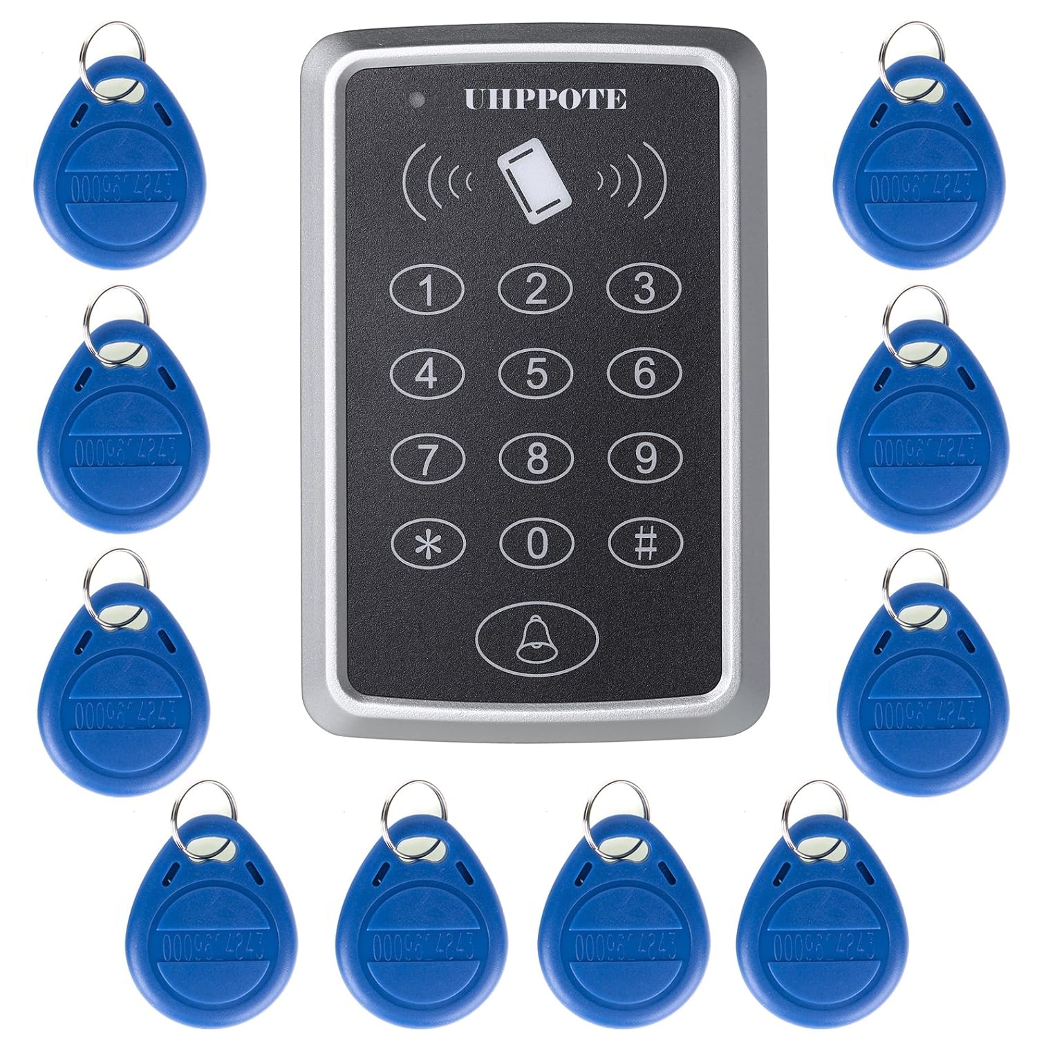
UHPPOTE 125KHz Single Door Proximity RFID Card Access Control Keypad Include EM4100 ID Keyfobs
Sensative Strips – Z-Wave Door and Window Sensors

The Sensative Strips claim they have a 10 year battery life time and they are super slim when compared to more traditional Z-Wave door and window sensors.
The round magnet is not used in the final installation but is used to wakeup the device during setup. The other oblong shaped magnet you can see is the one that is installed on the door or window frame along with the strip. When the contacts are broken the sensor is tripped etc.

Here you can see the rear of the strip.

Here is the purchased RFID keypad, hooked up to a 12V power supply for testing. The first thing I did was follow the instructions that came with the keypad to reset the default passcodes and I then assigned / setup four of the supplied keyfobs, it comes with ten fobs in total.

The instructions that come with this RFID keypad and straight forward and fairly easy to follow. There is a constantly flashing red LED light on the front of the keypad when it is powered up, when an assigned keyfob is held up to the keypad or the correct passcode is entered, the light goes green, “Access Granted”. When an unassigned keyfob or incorrect passcode is entered the light goes solid red and the keypad bleeps three times, “Access Denied”.
I bought a power supply off eBay to power the RFID keypad and also to power the Fibaro Universal Binary Sensor which is needed to make the RFID keypad visable and work with the Z-Wave network, more about that later.
Universal 12V 2A Switch Power Supply Source Driver Adapter For Led Strip Light
Specifications:
Input Voltage: 100~240V AC
Output Voltage: 12V
Output Current: 2A

So as I mentioned you also need a Fibaro Universal Binary Sensor, this is used to connect the RFID keypad to the Z-Wave network / controller.

The RFID keypad has two wiring connectors. JP1 and JP2.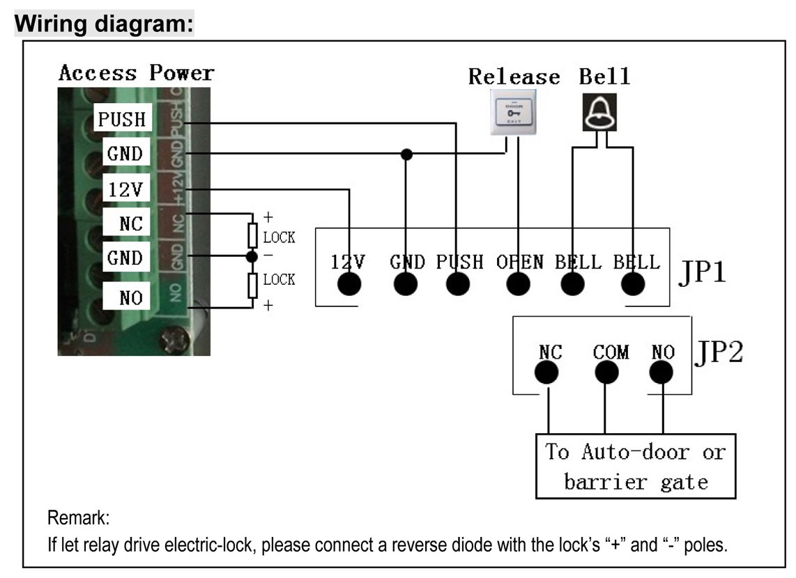
Here are the wires on the Fibaro Universal Binary Sensor.

The following is the correct wiring.
Wiring up the power for the keypad and the binary sensor:
| KEYPAD | Fibaro Binary Sensor | 12v Power Supply |
| JP1 12V (Red wire) | P (Red wire) | V+ |
| JP1 GND (Black wire) | GND (Blue wire) | V- |
Wiring for the keypad / binary sensor functions:
I connected the grey and the blue wires off the keypad to the blue wire on the binary sensor (The second GND wire) which is the blue wire below the ANT one in the diagram above.
| KEYPAD | Fibaro Binary Sensor |
| JP1 BELL (Grey wire) | Second GND (Blue wire) |
| JP2 COM (Blue wire) |
Here you just connect the white wire and the yellow wire together.
| KEYPAD | Fibaro Binary Sensor |
| JP1 BELL (White wire) | IN1 (Yellow wire) |
Here you just connect the brown and green wires together.
| KEYPAD | Fibaro Binary Sensor |
| JP2 NC (Brown wire) | IN2 (Green wire) |
I just taped the correct wires up together as you can see in the below picture, you might be able to use a small connector block, but remember you need to squeeze the binary sensor and all this wiring in to the back of the RFID keypad when mounted on the wall.

I then included the Fibaro binary sensor in to the Vera controller and changed a parameter for the device and tested it was working but more on that later.
My RFID keypad was to be wall mounted in my little porch area, there is a stud parition wall and the other side of this is my living room. You can see in the next picture, I already had a switched fused spur socket at the bottom of this wall for my outside porch light. So to feed power to the 12V power supply, I took the Live, Neutral and Earth from the back of the fused spur and connected them up to the 12V power supplies AC inputs. Then the power supplies DC outputs (V+ and V-) then connect up to the keypad / binary sensor etc.
I hid the 12V power supply in the stud wall. I couldn’t be bothered to chase out the wall to hide the alarm cable I used to connect the DC from the power supply to the keypad / binary sensor, so I just surfaced mounted the alarm cable along the bottom of the wall and up.

Here you can see the area where the keypad was to be mounted, next to a Z-Wave light switch.

Here is the keypad fitted with the Fibaro binary sensor hidden inside the keypad. I used a bit of double sided sticky pad on the back of the small Fibaro binary sensor and stuck it to the circuit board of the keypad so the two would not be touching each other.

The bell button is pressed when leaving the house to arm the system and when returning home the RFID keyfobs are used or you can use your passcode. I had to cut out a bit of the keypads plastic casing to allow the cable to come in from the side.

Now the actual physical installation is finished I will show you some of the basic setup in the Vera Z-Wave controller. You need to incude your door / window sensors in Vera if they are not already. For the Sensative Strips I used the Vesternet guide here. One thing they don’t mention in the guide is that the Sensative strips by default will not appear in the Vera UI7 Dashboard –> My Modes –> Choose Sensors to arm area, so you can arm or disarm the door sensors with Vera UI7’s default house modes. To do this see this thread here.

You also need to include the Fibaro Universal Binary Sensor in to Vera if you haven’t already. I didn’t take a screen shot of how the universal sensor looks in Vera by default, but you end up with three new devices and I have renamed mine.
“Alarm Keypad” is the master device. “Alarm Keypad Away” and “Alarm Keypad Entry” are the IN1 and IN2 of the binary sensor, these are child devices.

We must make a parameter change for the IN1 device, to make it normally open rather than normally closed.
From the user manual:
Parameter No. 3 - Type of input no. 1:
- Default value: 1 – INPUT_NC (Normal Close) Possible parameter settings:
- 0 – INPUT_NO (Normal Open)
- 1 – INPUT_NC (Normal Close)
- 2 – INPUT_MONOSTABLE
- 3 – INPUT_BISTABLE
So on the master device in my case its called “Alarm Keypad” go to the Device Options area and select the “Add Configuration Settings” button
Then enter Variable = 3. Data Size = 1 byte dec. Current Value = 0. Save the changes and let Vera reload.

When you press the bell button on the RFID keypad the “Alarm Keypad Away” device should go red and be tripped. When you swipe your keyfob or enter the correct passcode the “Alarm Keypad Entry” device should go red and be tripped. We can then use these new devices as triggers in our Vera scenes or PLEG logic to create whatever actions we want to happen for your alarm system.
The main thing you will need to setup is an entry timer delay, says 60 seconds to give you enough time to open the ARMED door and then to be able to swipe your keyfob to cancel the alarm siren from sounding. I wanted to do this in PLEG using the alarm example in the PLEG basics users guide, this uses state variables, however in the latest version of PLEG it seems state variables are broken and not working. So the only work around I could figure out for creating an alarm entry timer was to install the CountDown Timer plug-in for Vera and use the example found here.
In addition I have two native scenes in Vera called “Home” and “Away” I added triggers to these scenes using the new “Alarm Keypad Entry” and “Alarm Keypad Away” devices. I also added some lua code in to these scenes to also change Vera UI7’s default house modes.
Code to change Vera to Home mode:
luup.call_action("urn:micasaverde-com:serviceId:HomeAutomationGateway1","SetHouseMode", {Mode = 1}, 0)
Code to change Vera to Away mode:
luup.call_action("urn:micasaverde-com:serviceId:HomeAutomationGateway1","SetHouseMode", {Mode = 2}, 0)
I also have two futher native scenes in Vera, one called “Burglar Alarm” which is triggered when an armed door sensor is tripped, this is is the scene that starts the 60 second CountDown Timer, for your entry delay. The second scene is called “Burglar Alarm Delayed” its trigger is that the count down timer has completed (i.e. you have NOT deactivated your alarm) and this is the scene that would then sound the siren etc. But if you do within the 60 seconds swipe your keyfob this runs the “Home” Scene and this scene should cancel the count down timer etc therefore stopping the “Burglar Alarm Delayed” scene / siren from being triggered.
So now you can get creative, my alarm scenes also do the following for example. If the alarm is tripped and its night time, all the lights inside and outside of the house are turned on. The lounge curtains are opened and the LAPD flashing police lights are started on the LED strips lights behind my wall mounted TV, I am using a Fibaro RGBW module to control the LED lights in Vera. Also a TTS notification is sent to my mobile phone using Vera Alerts that the alarm has been activated.
When we are coming home and we swipe a keyfob to turn off the alarm, if its night time lights downstairs are automatically turned on for our entrance so we are not walking in to the house in the dark etc.
Conclusion
This is not a dedicated security alarm system, but if you don’t have such an alarm system installed and you want some basic protection on your door or windows and you already have a Z-Wave based home automation controller this could be a good fun project! Its also easy to use for the wife and kids leaving and entering the house, if they are the last ones leaving or the first entering the house.
If you wish to purchase any Z-Wave Euro devices at discounted prices then contact us via our website. www.asmarterhome.co.uk