
Today I installed a Fibaro Dimmer 2 module for my living room ceiling lights, so I took some photographs and thought I’d do a blog write up.
The Fibaro Dimmer 2 is a small wireless Z-Wave module that is installed behind light switches to make them “smart”. We can then control the lights wirelessly in the home automation system.
This will enable us to control the lights via our smart phones and tablet devices using the ImperiHome mobile app. We can then also setup scenes and schedules to have the lights automatically come on and off at certain times if we wish, or to simulate house occupancy when we are away.
Another function with scenes for example, could be if a Z-Wave smoke or C02 sensor was triggered in the night we could have the scene automatically turn on the lights to aid our escape or another example might be if our burglar alarm scene was tripped in the night we could also automatically turn on the lights inside and outside of the house when this happens.

Supported Loads
As a dimmer it operates under the following loads:
• 230V operated conventional incandescent and halogen light
sources
• 12V operated ELV halogen lamps and dimmable LED bulbs (with
electronic transformers)
• 12V operated MLV halogen lamps (with ferromagnetic
transformers)
• dimmable LED bulbs
• dimmable compact fluorescent CFL tube lamps
• supported dimmable light sources (power factor > 0.5) with
minimal power of 5VA using FIBARO Bypass 2 (depending on the
type of load)
Without dimming function it may work with:
• compact fluorescent CFL tube lamps with electronic ballast
• fluorescent tube lamps with electronic ballast
• LED bulbs (power factor > 0.7)
• supported light sources (power factor > 0.5) with minimal power
of 5VA using FIBARO Bypass 2 (depending on the type of load)
I am using a light fitting that has a 240v –> 12v transformer built in to it and I am using 4x new MR16 ECO low energy 14W halogen bulbs.
The Fibaro Dimmer 2 has a minimum load of 50W. So my 4x 14W halogen bulbs are 56W total, which is OK as I am over the 50W minimum. However if the total of your bulbs wattage is less than 50W, perhaps you are using low wattage LED bulbs, then you will also need to also install a Dimmer Bypass 2 as well. I’d say its probably best to install the Bypass 2 device as a matter of course anyway.

“The Fibaro Dimmer Bypass 2 acts as an intelligent load in the lighting circuit and will help prevent the LEDs flickering at startup, low dim settings or when they should be Off. The dimmer bypass should be installed in one of the light fittings or in the wiring going to the light fitting, it must be connected between the light's Live and Neutral wires. You only need one Dimmer Bypass 2 for each circuit (not for each light bulb).”
There are several excellent application notes from the guys at Vesternet about the Dimmer 2:
- Installing a Fibaro Dimmer 2 Module into a Wall Light Switch
- Using Fibaro Dimmer 2 with LED Lights
- 2-Way Lighting Using Fibaro Dimmer 2
- Using Different Switches with the Fibaro Dimmer 2
- Using a 3-Position Switch with a Fibaro Dimmer 2

I took it apart to take a closer look at the inbuilt 240v –> 12v transformer

I didn’t install a Bypass 2 as my bulb wattage total was over 50W and I don’t plan to use LED bulbs anytime soon.
For the Fibaro Dimmer 2 module to fit behind the light switches I recommend using 35mm back boxes. I also recommend replacing your existing light switches with 3-position momentary, or retractive, switches, these have 3 positions and are also known as an ON/OFF/ON switch.
Why use a 3-position Switch
This type of switch provides another way of controlling the Fibaro Dimmer 2 (and the light it is connected to):- Top ON
- Press once and release - turns light onto full brightness or previously set dim level
- Press and hold - increases brightness, releasing it keeps the lamp at that brightness
- Bottom ON
- Press once and release - turns light off
- Press and hold - decreases brightness, releasing it keeps the lamp at that brightness
Installation and Configuration
The switch and Dimmer 2 module can be connected to the lighting system as follows.Using a 3-Position Switch with a Fibaro Dimmer 2
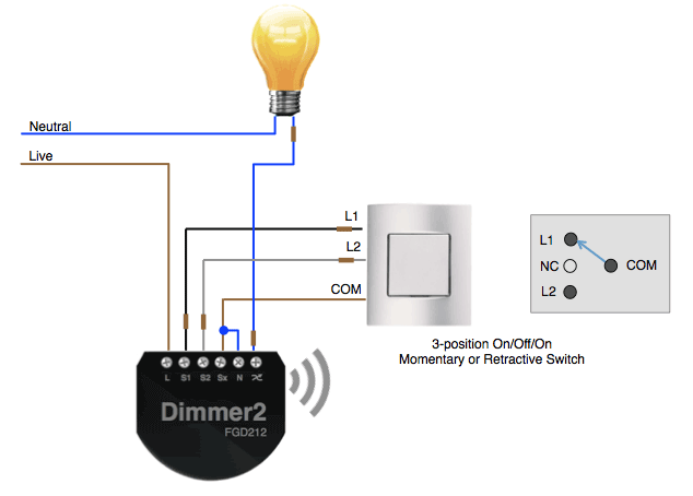
I wired up my Fibaro Dimmer 2 as per the wiring diagram above. I am using the Scolmore Minigrid 3 position momentary switches.


Here you can see the Fibaro Dimmer 2 module

Here is my orginal bog standard dimmer switch minus the screws which I had already took out.

Most UK light switch back boxes are likely to be only 16mm deep, so this means you will need to replace the back box with a deeper 35mm one.
Or you can buy light switch spacers to bring out the light switch away from the wall and then give you more space behind, but I am not keen on that look.
Here is the existing dimmer switch wiring, the wiring in my house is quite old done when the house was built in the 70s. Most UK light switches are a 2 wire system with no neutral.
The Fibaro Dimmer 2 module however supports both 2 wire and 3 wire systems.

I turned off the electric at the consumer unit for the lighting ring and disconnected the original dimmer switch.

I then proceeded to remove the 16mm back box, unfortunately I rushed this a little and some of the surrounding plaster work came away. I am sure if you take your time and are more careful than I was you can remove the back box with less damage.

I then proceeded with the hammer and chisel to knock out the block work deeper to fit the new 35mm metal back box.

Next I started connecting the Fibaro Dimmer 2 module and the new Minigrid switch.


Once wired in I applied my first lot of wall filler to fix the holes I had made.

I will later sand this down and apply a second lot of filler to make the job nice and neat and then use a little more white paint to finish.


You then need to pair the new Fibaro Dimmer 2 to the Vera home automation controller, I won’t cover how to do that here as its pretty standard stuff.
Once paired I then had 3 new devices in the Vera web GUI, two are child devices which I will hide from the GUI later as they are not needed. I renamed the main parent device to “Lounge Lights”.

When the Fibaro Dimmer 2 module is first powered on it runs an auto calibration routine to work out what type of lighting system / bulbs are in use and to automatically configure the minimum and maximum brightness levels.
In the device options I had to to set parameter 20 to 1 byte Dec with a value of 2. This tells the Dimmer 2 I am using the 3 position momentary type of light switch and sets it up in that mode etc.
Also you can add paramaters 1 and 2 to see the minimum and maximum brightness levels detected by the calibration routine. Mine were 1 and 82.

If you wish you could for example set parameter 2 to 70, so that when the light is on 100% in the GUI it is actually only using 70% brightness, this is another way to save yet more energy
consumption.

In the end after playing around with these parameters for a while I finally set parameter 2 to 80.
Here are the device controls in the Vera UI7 web GUI.


I then added the device in to the ImperiHome mobile application on all of our smart phones and tablet devices.

Summary
The Fibaro Dimmer 2 is a retro fit wireless Z-Wave lighting controller and is an essential part of any Z-Wave home automation installation. They make your home lighting “smart” and gives you the home owner added benefits of energy saving, security and control.


